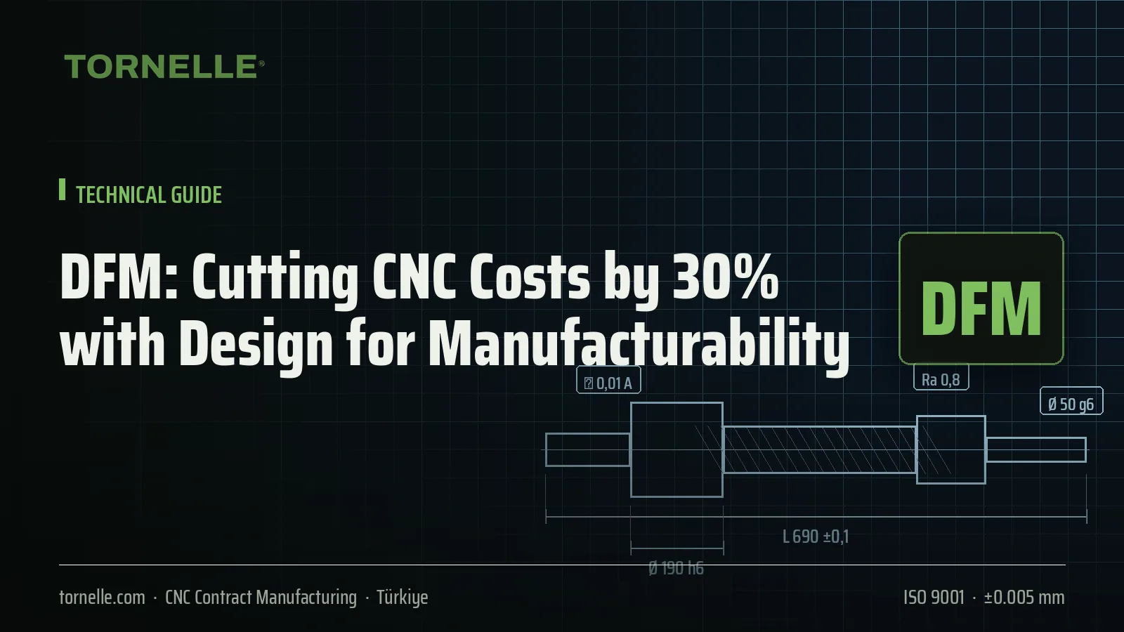
Contract manufacturers can quote prices that differ by a factor of two for two parts that perform the same function; the difference is not in the machine but in the drawing. Design for manufacturability (DFM) ensures that the part can be produced with the fewest operations, the fewest set-ups, standard tooling and standard material while preserving its function. The rules below are the designer-side counterpart to our article on the 12 factors that determine the price and are compiled from the DFM feedback Tornelle gives its customers at the quotation stage.
A. Geometry Rules
1. Match internal corner radii to standard tool diameters
In milled pockets the internal corner radius should be slightly larger than the radius of the end mill to be used: R3.5 or R4 instead of R3, R5.5 or R6 instead of R5. A radius equal to the tool radius causes full tool contact in the corner and chatter; a smaller radius means a smaller tool and much longer machining time. A sharp internal corner (R0) cannot be milled; if required, a relief hole in the corner or EDM is planned.
2. Limit pocket depth to 3–4 times the tool diameter
Deep, narrow pockets require long, thin tools; deflection, chatter and poor surface finish result. If the depth/width ratio exceeds 4, machining the pocket from both sides or widening it reduces cost.
3. Keep wall thickness in metals to at least 0.8–1 mm, preferably 1.5 mm
Thin walls flex during machining, do not hold tolerance and are machined at low speed. Walls below 1 mm in aluminium and below 1.5 mm in steel require a special strategy.
4. Limit hole depth to 5 times the diameter
Standard drills are designed for 3–5×D; 8–10×D holes require special long drills, peck drilling and low feed. Very deep holes can be drilled from both sides or the diameter can be increased.
5. Use standard hole diameters
Standard drill and reamer diameters such as Ø6.5 instead of Ø6.35, Ø10 or Ø10.5 instead of Ø10.2 save both tooling and time. Toleranced holes (H7) require reaming or boring; instead of writing H7 on every hole, write it only on functional holes.
6. Keep threads standard and shallow
When thread depth exceeds 1.5 times the diameter, strength does not increase, but the risk of tap breakage and the time do. Avoid threads below M3 and special pitches; in blind holes leave sufficient clearance at the bottom of the thread for the tap.
B. Tolerance and Surface Rules
7. Apply tight tolerances only to functional dimensions
A tolerance of ±0.01 mm can increase machining time and inspection cost 2–3-fold compared with ±0.1 mm. For general dimensions ISO 2768-m is sufficient; apply tight tolerances only to bearing, fit and assembly surfaces.
8. Specify surface roughness per surface
Instead of writing Ra 0.8 for the whole part, write Ra 0.8 on sealing and bearing surfaces and Ra 3.2 on the rest. Ra 0.4 and below requires grinding or polishing; question whether it is really necessary.
9. Define geometric tolerances with measurable datums
Geometric tolerances without datums or defined in a way that cannot be measured make both manufacturing and inspection ambiguous. If the datum surfaces coincide with the surfaces on which the part is clamped in the machine, the tolerance holds naturally.
C. Operation and Set-up Rules
10. Reduce the number of set-ups
Every additional set-up means set-up time, loss of reference and tolerance stack-up error. Having all features accessible from one or two faces can reduce cost by 30–50% compared with a housing machined from 6 faces. For turned parts with operations on the front and back, a twin-spindle lathe or a Swiss-type lathe finishes them in a single cycle.
11. Leave a clamping surface and a reference
Free-form parts machined on all sides have no surface to hold; designing a small clamping pad or a stem that is cut off afterwards saves the cost of a special fixture.
12. Question unnecessary operations
Features such as cosmetic milling on hidden surfaces, non-functional chamfers and R0.5 rounding on all edges extend machining time. The note "break all sharp edges" is far more economical than writing a separate chamfer dimension on every edge.
D. Material and Stock Rules
13. Design to standard bar and plate sizes
Producing a Ø29.8 part from Ø30 bar is ideal; a Ø31 part means Ø35 bar and extra chips. The same rule applies to plate thicknesses (10, 12, 15, 20, 25 mm); an 18 mm thickness requires removing 2 mm from 20 mm plate.
14. Consider easier-to-machine material alternatives
If the corrosion or strength requirement allows: 304 instead of 316L, 303 instead of 304; 6082 instead of 7075; free-machining steel (11SMnPb30) instead of general steel. Machining time is shortened by 20–50%. Our stainless steel and aluminium guides contain the selection criteria.
15. Account for coating and heat treatment in the design
Hard anodising (25–60 µm) and coatings change dimensions; specify the tolerance as "after coating" or "before coating". On parts where distortion is expected after heat treatment, leave a grinding allowance on critical dimensions.
How to Hold a DFM Discussion with Your Contract Manufacturer
The best time is the quotation stage, before the design is frozen. When sharing the STEP file and drawing, add the note "we would like DFM feedback"; a good supplier lists the cost-increasing features and its recommendations together with the quote. Not every recommendation has to be accepted; features with a functional justification stay, those without are simplified. Tornelle provides this feedback as standard in the quotation process; for the process see our how we work page.
Frequently Asked Questions
How much saving is possible with DFM?
Between 10% and 40% depending on the part; the biggest gains come from unnecessarily tight tolerances, excess set-ups and non-standard radii/diameters.
Does DFM feedback transfer design responsibility to the supplier?
No. The supplier makes recommendations; the decision and design responsibility remain with the customer, and accepted changes are documented with a drawing revision.
Is DFM necessary for prototypes?
Cost may be secondary for prototypes; however, for parts that will go into series production, doing DFM at the prototype stage prevents later revision and re-FAI costs.
Which file format is suitable for DFM?
STEP + PDF drawing is the ideal combination; STEP carries the geometry, PDF carries the tolerances and notes.
Conclusion
Design for manufacturability is the cheapest way to lower CNC cost: it simplifies the drawing instead of negotiating. Standard radii and diameters, selective tolerances, few set-ups and easy-to-machine material significantly reduce the unit price without changing the function. If you would like DFM feedback on your parts, send your STEP and PDF files via our quote form; the recommendations come with the quote.