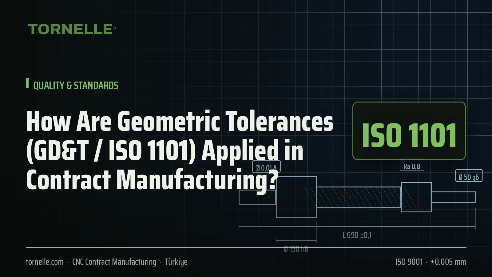
A dimensional tolerance states how much a diameter or length may deviate; a geometric tolerance states how much form, orientation and location may deviate. A large share of disputes in contract manufacturing arise not from size but from geometry: "The diameter is in tolerance but the hole is in the wrong place", "The face is not flat and wobbles in assembly". Following on from our ISO 2768 general tolerances article, this one explains how geometric tolerances are read, measured and priced on the supplier's side.
Two Systems: ASME Y14.5 (GD&T) and ISO GPS (ISO 1101)
American drawings follow ASME Y14.5, European drawings the ISO GPS family (ISO 1101, ISO 5459, ISO 2692, ISO 8015). The symbols are largely identical; the differences lie in the principles: under ISO 8015 the independency principle applies (size and form tolerances are independent of each other), whereas in ASME Rule #1 means the size tolerance also limits form (envelope principle). Turkish shops read both systems, but the standard the drawing follows must be stated in the title block. If it is not, the supplier asks; if it does not ask, that is a potential problem.
The Most Common Geometric Tolerances
| Tolerance | What it controls | Typical application | Measurement |
|---|---|---|---|
| Flatness | Surface lies between two parallel planes | Sealing faces, mounting bases | Granite + dial indicator, CMM |
| Cylindricity / circularity | Closeness of section and whole surface to a cylinder | Bearing surfaces, pistons, valve spindles | Roundness tester, CMM |
| Perpendicularity / parallelism | Orientation of a surface or axis to the datum | Flange face to bore axis, guide faces | CMM, indicator + square |
| Position | Deviation of a hole/axis from its theoretical location | Hole patterns, pin holes | CMM, position gauge |
| Coaxiality / concentricity | Coincidence of two axes | Stepped shafts, bushings | CMM, indirectly via runout |
| Runout (circular / total) | Surface deviation about the axis of rotation | Shaft surfaces, gear seats | Between centres + indicator |
| Profile (line / surface) | Conformity of a free form to the theoretical profile | Cams, blades, ergonomic surfaces | CMM scanning, optical |
Datum Logic: No Reference, No Tolerance
Location, orientation and runout tolerances require datums (references). The datum system in order A-B-C defines how the part is fixed during measurement: the primary datum constrains 3 degrees of freedom, the secondary 2, the tertiary 1. In contract manufacturing, datum selection is critical for two reasons: the supplier tries to clamp on the same surfaces when machining (functional datum = machining reference is the ideal) and measures from the same datums in the inspection report. If the drawing has no datums, the supplier chooses its own reference; results that disagree with your measurements originate here. Our CMM report article explains the effect of datum alignment on results.
Material Condition: MMC, LMC and Bonus Tolerance
If the position tolerance frame carries the Ⓜ (MMC, maximum material condition) symbol, the position tolerance gains a "bonus" as the hole grows from its smallest diameter: a Ø0.1 position tolerance at MMC for a Ø10 H9 hole becomes Ø0.136 if the hole is machined at Ø10.036. For the assembly function (bolt clearance) this is entirely logical and gives real relief in manufacturing. If the feature is unnecessarily left at RFS (Ⓢ / unmarked), the supplier cannot use the bonus and the price rises. Using MMC for bolt clearance holes is one of the simplest DFM gains; our DFM article has further examples.
Effect of Geometric Tolerances on Cost
- Measuring time: A position tolerance requires a CMM programme; for a sample of 1–5 pieces this can take longer than machining.
- Machining strategy: A stepped shaft requiring 0.01 mm coaxiality must be finished in one set-up (mill-turn or sub-spindle lathe); with two set-ups the value is left to chance.
- Datum mismatch: If the machining reference differs from the functional datum, the supplier adds an intermediate operation (preparing a reference surface).
- Total runout and cylindricity of 0.005 mm and below: Requires grinding or finishing after heat treatment; a separate line item in the contract price.
Rule: A geometric tolerance should be where the function requires it and as tight as the function requires. Writing Ø0.05 position tolerance on every hole of a drawing makes the part 20–40% more expensive and is usually unnecessary. Our tolerance selection article discusses this balance.
Mistakes Made When Sending Drawings to a Supplier
- Not specifying the standard (ISO 8015 or ASME Y14.5).
- Giving a position tolerance without defining datums.
- Choosing an unmachined (raw) surface as a datum.
- Writing ISO 2768-mK as the general tolerance without knowing the geometric meaning of class K (class K values apply for flatness, perpendicularity, runout).
- Leaving a different tolerance in the PDF while the 3D model carries PMI (product manufacturing information); when the two sources conflict the supplier does not know which to follow.
- Not specifying the measuring method: is runout measured between centres or on V-blocks? Results can differ.
Verification on the Supplier's Side
A good contract supplier lists geometric tolerances separately at quotation stage and states which equipment will measure them. The first-article report (FAI) must show the measured value, the datum alignment method and the instrument used for every geometric tolerance. In series production, critical geometric characteristics are placed in the control plan and sampled at a defined frequency; 100% measurement is only economical with functional gauges (position gauge, go/no-go).
Discussing GD&T with a Contract Supplier
Geometric tolerances are the most misunderstood topic at quotation stage; clarifying the following points with the supplier prevents most later disputes:
- Which standard applies? The default rules differ between ISO GPS (ISO 1101, ISO 5459, ISO 8015) and ASME Y14.5; it must be stated in the title block, and the supplier should say which rules it measures by.
- Measuring method: Position and profile tolerances require a CMM; runout and coaxiality can be measured with an indicator and rotary table. See in the control plan which feature the supplier measures with which instrument.
- Machinability of datum surfaces: The surface chosen as datum A must be usable as the supplier's clamping surface; making a cast surface or a small shoulder the datum increases measurement uncertainty.
- Reporting format: Geometric tolerances should be reported with the actual measured deviation and the tolerance zone; "OK" alone is not sufficient.
- Cost effect: Ask explicitly how much tightening a tolerance from 0.05 to 0.02 mm will raise the price; a good supplier tells you which feature really drives cost and proposes alternatives.
This discussion usually takes place in a 20-minute video call and ensures first-article approval passes the first time; afterwards only critical features are monitored in series batches.
Frequently Asked Questions
My drawing has no geometric tolerances — is that a problem?
If a general tolerance standard (such as ISO 2768-mK) is stated, there are limits for geometric deviations too. On functionally critical surfaces you are still advised to give explicit tolerances; otherwise there is a risk of "in tolerance but does not assemble".
Which instrument does the supplier use to measure position tolerance?
CMM for samples and small batches; in series production CMM sampling according to the control plan plus functional gauges.
Do ISO and ASME drawings give different results?
The same symbol can give a different acceptance result under different principles (independency/envelope). Stating the drawing standard removes this ambiguity.
Does using MMC reduce quality?
No; MMC defines the real tolerance tied to the function (assembly clearance). It does not reduce quality, it reduces unnecessary rejects.
Conclusion
Geometric tolerances establish a common language with the supplier in contract manufacturing: the right datums, the right standard and tightness appropriate to the function reduce both measurement disputes and cost. Send your drawings with geometric tolerances via our quote form; together with the quote we state the measuring method and report scope. For our quality approach see our how we work page.